Compound paths and you

Compound paths are a fundamental aspect of Illustrator drawing (and other vector drawing), but given the amount of questions I get about them at work, perhaps not intuitive to understand. I made this as a brief run-down of how compound paths work and how to work with them for my colleagues; maybe you’ll find it useful too.

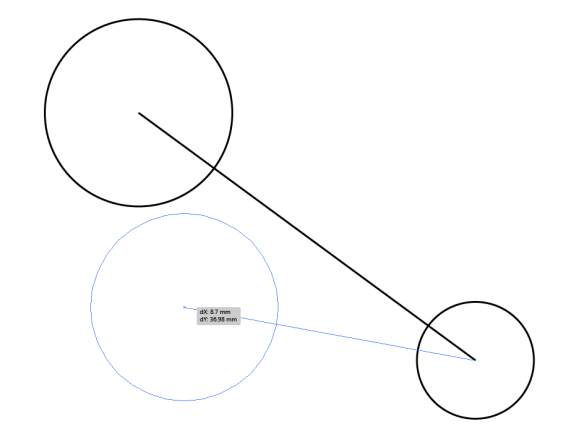
For the most part, compound paths are about making holes in things. Here the two circles become a compound path; the smaller circle cuts its area out of the larger one, and you can see the yellow box in the centre as a result.

Asset 1@2x-8

Make a compound path by selecting the objects you want to become one and use the menu via Object > Compound Path > Make, or press Ctrl + 8.

Asset 13@2x-8The Pathfinder can also be used to make compound paths. In this case, Minus Front and Exclude would have the same effect as above.

You can use any number of shapes of any complexity in a compound path with the same effect. You can also use shapes that overlap each other − but that’s where things get more complex.

Asset 3@2x-8

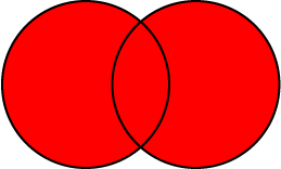
Here two overlapping circles form a compound path. The area of their overlap is excluded from the shape’s fill, as you might expect:

Asset 4@2x-8

But these circles are also a compound path, and their entire area is filled, including the overlap. What’s going on here?

Asset 5@2x-8

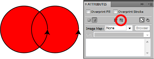
The answer lies in the relative directions of each circle’s path. Every path has a direction, usually going from its start point to end point. In closed shapes made with the shape tool, the direction is anticlockwise. Here I have given each circle an arrowhead so we can see the path direction:

Asset 6@2x-8

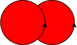
Compound paths, by default, use something called the Non-Zero Winding Fill Rule to determine which overlapping areas are filled and which aren’t. You can see this in the Attributes panel. In two newly-compounded shapes, the bottom one in the stack order will reverse direction, and the opposing directions of the two paths result in the overlapping area being excluded from the fill:

Asset 7@2x-8

You can change the direction of a path in the Attributes panel too. Direct-select one of the paths and use the Reverse Direction button (this only applies to paths as part of a compound paths; reversing the direction of regular paths is possible via the menu Object > Path > Reverse Path Direction). As the paths are going in the same direction, the rule determines that the overlapping space is filled:

Asset 14@2x-8

Note that shapes that have been ‘uncompounded’ (that is, released) appear to remember that they had their path directions altered and honour that setting − so effects like the lower path reversing direction might not occur if they are incorporated into other compound paths.

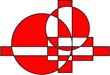
The Non-Zero Winding Fill Rule has a limitation shown here. What if three or more shapes overlap? They can’t all go in opposite directions, right? So some overlap areas end up filled while others aren’t.

Asset 8@2x-8

For situations like this, there is the Even-Odd Fill Rule. Here path direction is irrelevant and what matters is the number of objects that overlap. Odd numbers of objects will create filled areas, and even numbers unfilled areas.

Asset 9@2x-8

In some cases, it might be necessary to switch rules to ensure the effect you want, especially in objects with many shapes, where the Non-Zero Winding Fill Rule may create unpredictable results.

Asset 10@2x-8

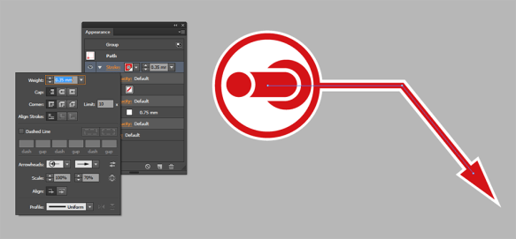
Consider this situation. There are several red shapes on top of the large red circle in the stack order, but a single green square below it. When you make a compound path from the shapes within the large circle’s area, only the bottom square is excluded from the fill and the whole lot becomes green! Why?

Asset 11@2x-8

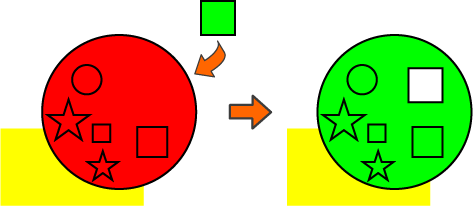
Remember that only the bottom shape in the stack order reverses direction, so every other shape has the same path direction as the large circle. And as we are now aware, the compound path takes on the appearance attributes of the bottom object.

Asset 12@2x-8

Switching to the Even-Odd Fill Rule in this case produces the desired result.

It’s these fill rules that seem to give users the most problems, especially if one of the inner objects was drawn first. If you do a few experiments and reinforce for yourself what each rule (and changing path direction) does, you’ll find yourself solving these problems without even thinking about it.

Fun with Zig-Zag Spirals

My initial reasons for hanging around the Adobe Illustrator forum was to look for puzzles; that is, things that people couldn’t work out how to achieve that I’d then have a think about and see if I could figure out. They’re squeezed in between complaints about Adobe CC and real beginner questions mostly, but every now and then one pops up. Here’s one I found recently that was quite satisfying to figure out:

How to make a hynpotic spiral (sic)

This person (who unfortunately never followed up their initial post) wanted to make something like the swirl of zigzags in this image (which I cannot credit, having no idea where it came from):

IMG_6544

I couldn’t think of a way right off the bat. Thinking about Illustrator’s own spiral tools and brushes was a dead end, as they introduce innaccuracy and distortion. But then I stopped thinking about it in terms of a spiral, because that’s not really what it is: it’s entirely a construction of straight lines, after all. So what is it made of? Well, what solved it for me was viewing it as a set of radiating lines.

radiate

Each pair of lines will be guides for the peak and trough of the zigzag. The zig and the zag, if you will. One is rotated slightly from the other an arbitrary distance based on how sharp you want your zigzags to be. Take the rotate tool and alt/option-click on the bottom end of your first line. Type in an amount in degrees (four in this case) and click on ‘copy’.

We want an amount that divides nicely into 360, so the pair of lines is then rotated and copied 20 degrees around the centre, so we end up with the image above.

The next stage is ending up with zigzags that shrink smoothly towards the centre of the image. To do this, we want to end up with a polar grid of sorts (but don’t bother with Illustrator’s polar grid tool – it won’t save any time here). All we want is a set of circles that increase in size by a percentage each time.

Screen Shot 2016-06-07 at 19.19.41

Start as close to the centre as you dare – the more circles in this grid, the more work you’ll have to do. I’ve scaled this one by 110% each time. At this stage it might be worth making the whole thing into guides – you won’t need these actual lines in the spiral, they’re just here as scaffolding. Now we need to draw our zigs and zags. Make sure smart guides (ctrl + U) are turned on for this.

Screen Shot 2016-06-07 at 19.29.59

There are probably other viable patterns, but to get something like the original image it’s best to go three down, one up. Use smart guides and draw paths using the ‘intersect’ indicator to make sure you’re hitting where the guides cross. Keep going until you get to the centre of the circle (I’m cheating here by going for wider zigzags).

As a shortcut, you could just draw the one nearest the centre, then scale and copy 110% from the centre point of the guides, just as we did with the circles. Either way, once you’re done with one row, copy 20 degrees around the centre again to end up with this beauty.

Screen Shot 2016-06-07 at 19.48.18

There’s some inaccuracy at very high zoom levels that I can’t quite work out; I think it may be to do with the inherent inaccuracy of bezier curve circles, but it doesn’t affect the next step too much so I’m not going to worry about it. First up make an outer circle (or other shape) to act as a bounding area for a live paint group. Then hide your guides, give all the lines no stroke, and go nuts with fill colours.

Screen Shot 2016-06-07 at 19.56.07

What I liked most about this is that, as a problem that could be solved with a pen and compass, this obviously must be a known solution. But as someone looking at this completely fresh, it felt good to come up with that on my own through experimentation.

Slings and arrowheads

I’ve seen a few posts on the Adobe forums from time to time asking how one might ‘attach’ objects or symbols to path endpoints (or anchor points in general), so that you might have elements that move as you move points around.

arrowheads1

Like a lot of things in Illustrator, this isn’t really possible, but there are a number of odd ways you can accomplish things that might do the job well enough. I had a need to do something similar at work; producing a sort of annotation symbol for use by people who didn’t really have any Illustrator expertise, so it needed to be as simple as possible to manipulate. I went with custom arrowheads.

arrowheads2

I’ve got the appearance and stroke open there so you can see what’s going on. If you don’t know how to create your own arrowheads, Adobe provide the bare minimum of information here. There’s more info in the arrowheads file itself, but nevertheless there are a bunch of odd pitfalls and ways of going wrong, exacerbated as I was a CC user making an arrowheads file for CS5 users too. But after a bit of a struggle I had a nice bunch they could use, with some caveats. Ideally I didn’t want anyone moving the leader line from the horizontal, as this would happen:

arrowheads3

…and having symbols flying off at different angles just looked kind of unprofessional. So I was left trying to figure out a way of having a symbol stuck to one end of a path that maintained its rotation relative to the page, rather than the path. The clue to what I did is in the wording there. It’s a silly method, but within the confines of the page we use it works perfectly. Scatter brushes!

arrowheads4

Note the spacing: 9999%. This means you’ll see one instance of the brush every 100 times the maximum dimension of the brush object. Over half a metre in this case! More than we’ll ever need in a document 100 mm wide. The other key option is to have the rotation set relative to the page, so it won’t rotate as you change the angle of the path. This means although this is rather an awkward solution, the users shouldn’t see any difference, except the style now works as they wanted. Here’s the new path with its appearance:

arrowheads5

The top stroke has the scatter brush applied, the next has the arrowhead at the other end and the red swatch. The next two define the white backing to the stroke and the arrowheads respectively.